Ukitecture System (1996)
CLIENT: Any port authority or marine developer.
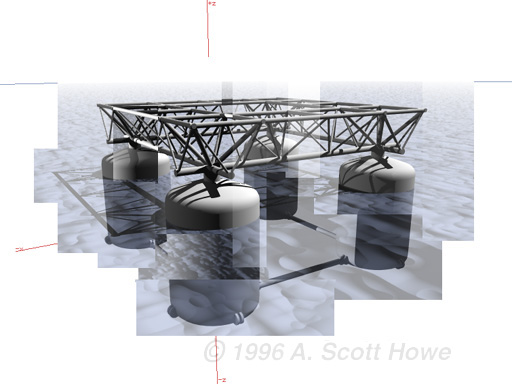
CONCEPT: The Ukitecture System consists of four main types of modules that can be assembled into a floating platform of unspecified length and width. The four modules are pontoon, node, truss, and brace. The node is a universal connector which mounts on top of the pontoon. The node consists of four sockets oriented orthogonally from each other, which act as waiting receptacles for the mounting of the trusses. The trusses are triangular in section with a double upper chord. Combined with the girders that form the top square of the node component, the double upper chord of the truss defines an implied flat surface ready to be built upon. The pontoon is designed to carry a worse-case scenario, which is four trusses plugged into all available node sockets, supporting a maximum load. The brace is an underwater girder which connects between the pontoons to provide added lateral structural support. Using the Ukitecture System, floating platforms can be assembled on site as needed. Due to the modular design of the components, expanding the size can be accomplished by adding new parts on the spot without interrupting business or vacating the existing platform. A system has been devised which allows the connection of new components and which also allows the replacement or periodic maintenance of existing pontoons.
The pontoons are placed at 20 meters on center and have a maximum draft of 9.5 meters for protected port anchorage (Ukitecture System is NOT designed for open ocean). Each pontoon has a maximum displacement of 490 tonnes. In the design draft condition, the pontoons extend 3 meters above water line with an additional meter to the bottom of the truss, allowing 4 meters clearance for small craft and the placement of docks and landings beneath the platform.
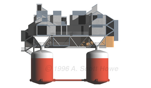
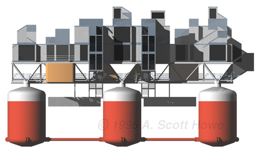
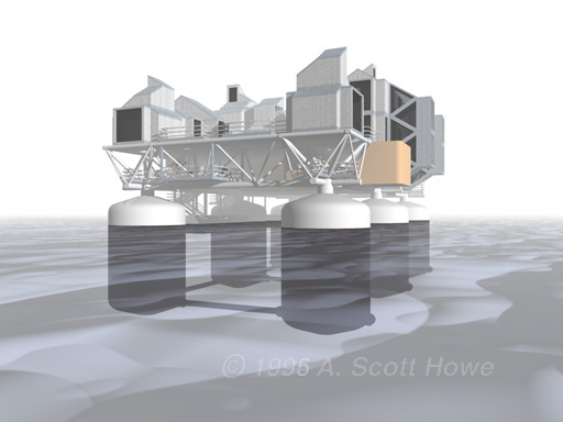
As an example architectural application, a steel moment frame / heavy timber kit-of-parts was conceived which can mount on the Ukitecture platform system and interface with its utility harness junction points. The kit-of-parts system uses a shape grammar that establishes a set of rules for space planning, connection, and interface with the Ukitecture platform. Two node-interfacing components, three space components, five roof elements, two stairway components, one landing component, four deck components, two catwalk components and four special wall elements were conceived for the kit-of-parts library. In addition, six plug-in modules containing complex plumbing or electrical fixtures (restrooms, kitchens, etc.) were devised. Using components from the kit-of-parts library, a floating restaurant / shopping mall facility was conceived as a route stop for the Sea Bass shuttle boat in Yokohama harbor (also accessible to yachts, small craft, and jet skiers). The facility has a 474m2 formal restaurant, a 82m2 fast-food restaurant, a 32m2 convenience store, a 32m2 bar, 44m2 of small shop space, and 19m2 of "yattai" space (yattai= a small portable food cart similar to a hot dog or popcorn stand). In addition, the facility has 297m2 of deck space for outdoor dining and dancing, and special decks for fishing enthusiasts.
DESIGN TEAM: Structure & architectural design, buoyancy calculations: A. Scott Howe. Marine Architecture advisor and consultant: Michael Parsons.
COST: None estimated.
DATE: Fall 1996.
STATUS: Only architectural, structural, and buoyancy design steps were taken.
Other images and animations:
flyby animation (3.7mb)
Ukitecture System paper (PDF)